

My Raspberry Pi Powered Commodore Plus 4
It's one thing having a collection of retro computer hardware that you don't want to risk actually using, mainly because old electronics are fragile, or it may need recapping (Amiga and BBC Model B, i'm looking at you), or you don't want to ruin your perfect childhood memories of waiting a long time for games to load from cassette and playing them on an old 19 inch black and white TV with slightly dodgy varicap tuning in your bedroom? So you turn to emulation on your computer, or maybe even Retropie on a Raspberry Pi.However, much like your first car, your first gaming system stays with you, and after some time, the whole experience of handling the real hardware needs to be relived. So what do you do..?Right then, what was my first system I used for playing games? A Binatone TV Pong game. Right. Ok. So what was my second, and most cherished system for playing more than eight similar variations of Pong with a monophonic "donk" sound on a black and white TV?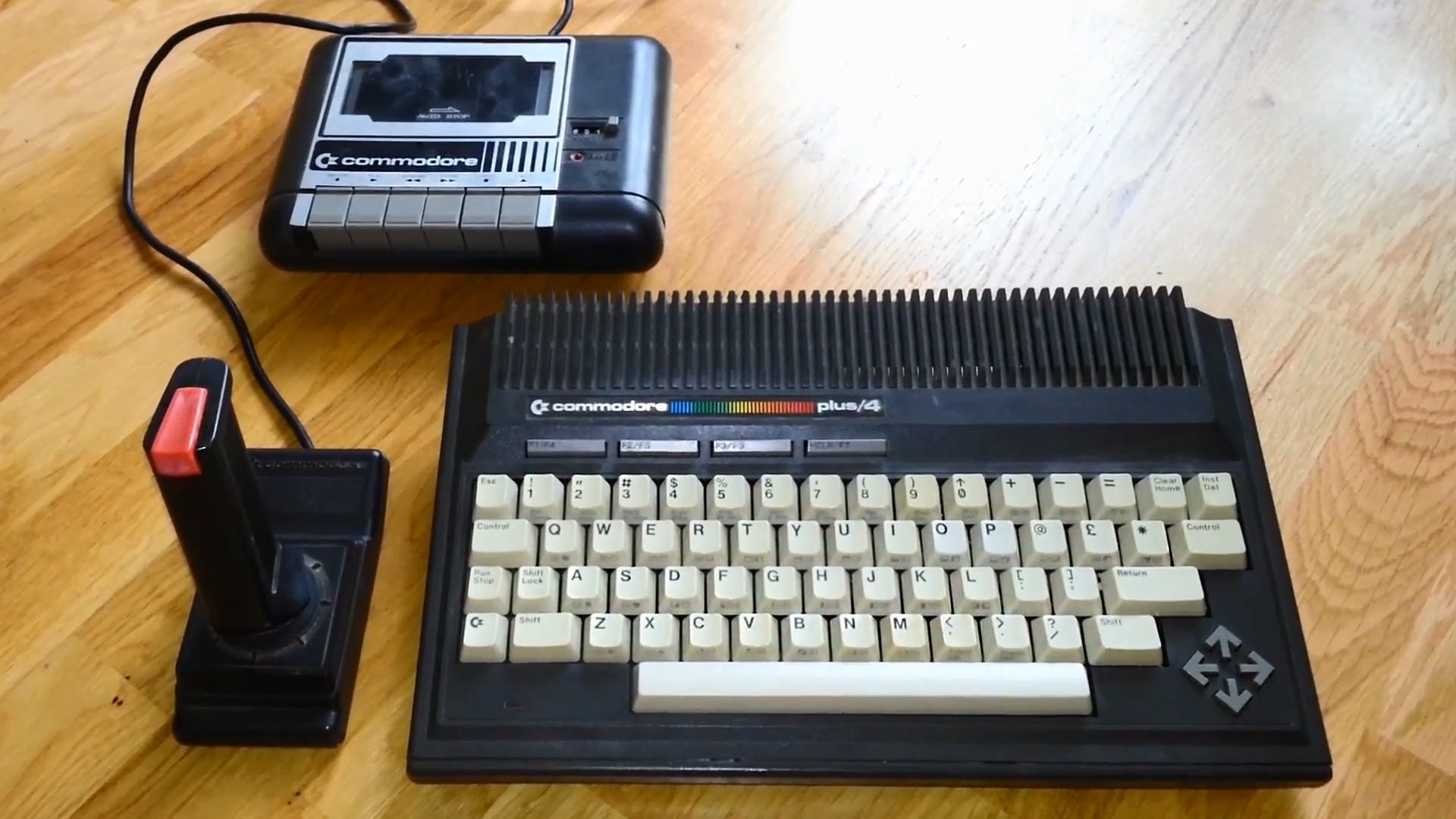 That's right, a Commodore Plus 4.Unfortunately both my Commodore Plus 4's have issues, one has a faulty TED chip which manifests itself by giving a "?SYNTAX ERROR" every time you try to do anything, and the other does nothing more than show a black screen, this is likely to be a dead CPU.If I could bring myself to swap chips around I might be able to make one working machine out of two
broken ones, but I don't want to, I'd rather go all out and put a Raspberry Pi in it.
Please note this is not an easy project, and is not recommended for absolute beginners.Some knowledge of soldering, dealing with components, and the Raspberry Pi is recommended.
Parts required.One (preferrably dead but complete) Commodore Plus 4Raspberry Pi (I used a Zero)MicroSD card (16GB is enough)5V power supply (Official one is best)Heatsink for the PiKeyrahV2Four port USB hubMini HDMI extension of suitable lengthUSB extension of suitable lengthMicro USB extension (short) or a micro socket to mini plugJoystick extension (optional X2)USB A to B cableUSB Ethernet adaptor or extensionMicro USB cable (you don't mind cutting up)Right angled pin headers and 20cm jumper leads (Dupont)Small piece of stripboard5V LED (Red for originality, I used a green one)Old style joystick with 9-pin D connector (or two)Plastic standoffs and plastic nutsCombian64 V2.5 software Version 2.5 Experimental was released afterwardsWin32DiskImager softwareCommodore C16/Plus 4 disk/tape/cartridge images
Tools requiredScrewdriversSoldering iron with solder and de-soldering braidMultimeterInsulating tapeSmall hobby drill with cutting disc, grinding disc and a selection of small drill bitsEpoxy glueStrong double sided tapeUSB keyboard for setting up purposesUSB memory stick for transferring of filesAccess to a PC with a SD card reader
Build planThe brief for this build is to create a realistic Commodore Plus 4 that behaves as close as possible to the original hardware WITHOUT modifying the case, so it can be put back to it's original form if a supply of TED chips become available. It must have the original switch and reset button which should work, the LED must work, there must be at least one standard 9 pin D type joystick port available, and a USB socket must be availableAs with all my projects, I will try to use what's in my parts drawer rather than buy in new.
Test procedureFirst thing is to make sure everything works as intended, so write the Combian64 image to the SD card, then put the heatsink on the Pi, put the card into the Pi then connect up all the leads and boot it up...The Pi will load up into the Vice C64 emulator pretty quickly, press F8 (yes F8 on Combian64) on an attached USB keyboard and select Exit from the Vice menu. You should now be looking at the Raspbian Lite login screen, although you will be automatically logged in as root.Type menu and the Combian64 menu will load, scroll down with the cursor keys and select COMMODORE PLUS/4, then OK, and then finally select RUN EMULATOR, this will start the Plus 4 emulator everytime you start the machine.
That's right, a Commodore Plus 4.Unfortunately both my Commodore Plus 4's have issues, one has a faulty TED chip which manifests itself by giving a "?SYNTAX ERROR" every time you try to do anything, and the other does nothing more than show a black screen, this is likely to be a dead CPU.If I could bring myself to swap chips around I might be able to make one working machine out of two
broken ones, but I don't want to, I'd rather go all out and put a Raspberry Pi in it.
Please note this is not an easy project, and is not recommended for absolute beginners.Some knowledge of soldering, dealing with components, and the Raspberry Pi is recommended.
Parts required.One (preferrably dead but complete) Commodore Plus 4Raspberry Pi (I used a Zero)MicroSD card (16GB is enough)5V power supply (Official one is best)Heatsink for the PiKeyrahV2Four port USB hubMini HDMI extension of suitable lengthUSB extension of suitable lengthMicro USB extension (short) or a micro socket to mini plugJoystick extension (optional X2)USB A to B cableUSB Ethernet adaptor or extensionMicro USB cable (you don't mind cutting up)Right angled pin headers and 20cm jumper leads (Dupont)Small piece of stripboard5V LED (Red for originality, I used a green one)Old style joystick with 9-pin D connector (or two)Plastic standoffs and plastic nutsCombian64 V2.5 software Version 2.5 Experimental was released afterwardsWin32DiskImager softwareCommodore C16/Plus 4 disk/tape/cartridge images
Tools requiredScrewdriversSoldering iron with solder and de-soldering braidMultimeterInsulating tapeSmall hobby drill with cutting disc, grinding disc and a selection of small drill bitsEpoxy glueStrong double sided tapeUSB keyboard for setting up purposesUSB memory stick for transferring of filesAccess to a PC with a SD card reader
Build planThe brief for this build is to create a realistic Commodore Plus 4 that behaves as close as possible to the original hardware WITHOUT modifying the case, so it can be put back to it's original form if a supply of TED chips become available. It must have the original switch and reset button which should work, the LED must work, there must be at least one standard 9 pin D type joystick port available, and a USB socket must be availableAs with all my projects, I will try to use what's in my parts drawer rather than buy in new.
Test procedureFirst thing is to make sure everything works as intended, so write the Combian64 image to the SD card, then put the heatsink on the Pi, put the card into the Pi then connect up all the leads and boot it up...The Pi will load up into the Vice C64 emulator pretty quickly, press F8 (yes F8 on Combian64) on an attached USB keyboard and select Exit from the Vice menu. You should now be looking at the Raspbian Lite login screen, although you will be automatically logged in as root.Type menu and the Combian64 menu will load, scroll down with the cursor keys and select COMMODORE PLUS/4, then OK, and then finally select RUN EMULATOR, this will start the Plus 4 emulator everytime you start the machine.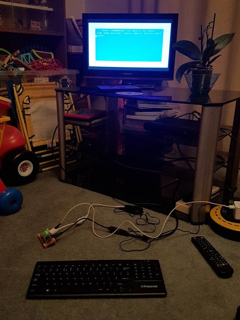 Of course there's no reason why you can't set up the C64 and Vic 20 machines as well, there's no playground rivalry here.Connecting the KeyrahV2 via USB won't achieve much at the moment.Once you're happy it works, shut it down by exiting the emulation as before and then typing shutdown now, wait until the TV shows "No signal", then take it all apart and put it to one side.
Plus 4 disassemblyUnscrew the five screws that hold the Plus 4's case together, gently remove the ribbon cable from the circuit board, then unscrew the six screws that hold the board to the bottom case.
Of course there's no reason why you can't set up the C64 and Vic 20 machines as well, there's no playground rivalry here.Connecting the KeyrahV2 via USB won't achieve much at the moment.Once you're happy it works, shut it down by exiting the emulation as before and then typing shutdown now, wait until the TV shows "No signal", then take it all apart and put it to one side.
Plus 4 disassemblyUnscrew the five screws that hold the Plus 4's case together, gently remove the ribbon cable from the circuit board, then unscrew the six screws that hold the board to the bottom case.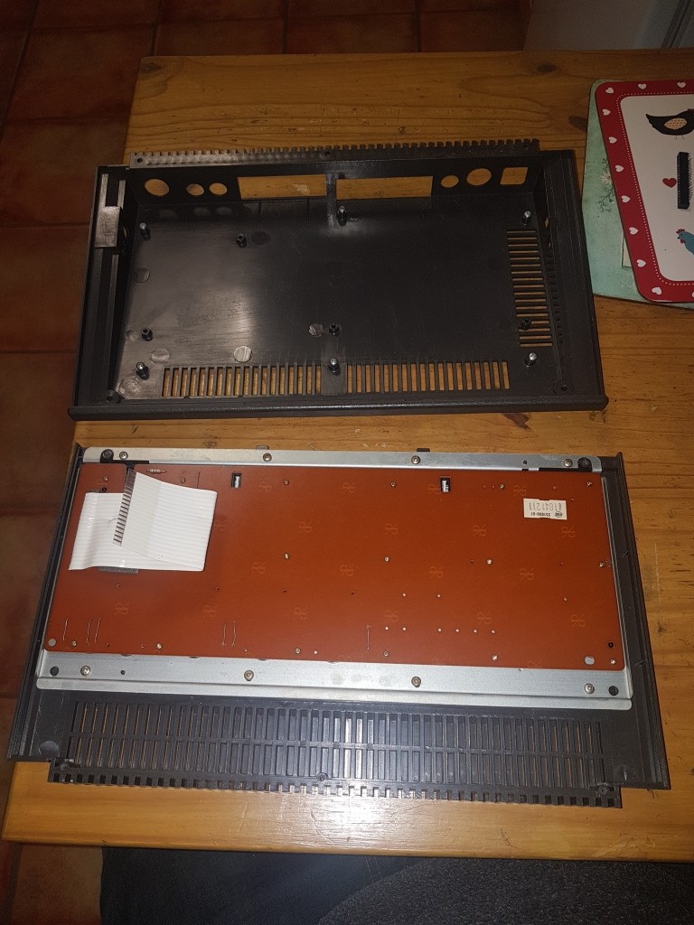 I wanted to reuse the original switch and reset button, so these were carefully unsoldered from the board and mounted on a small piece of stripboard as in the photo, the components almost exactly line up with original holes, I did have to slightly enlarge the holes on the stripboard for the switch pins.The pin header you can see is the connections for the switch and button. I modified this arrangement for the final fit.
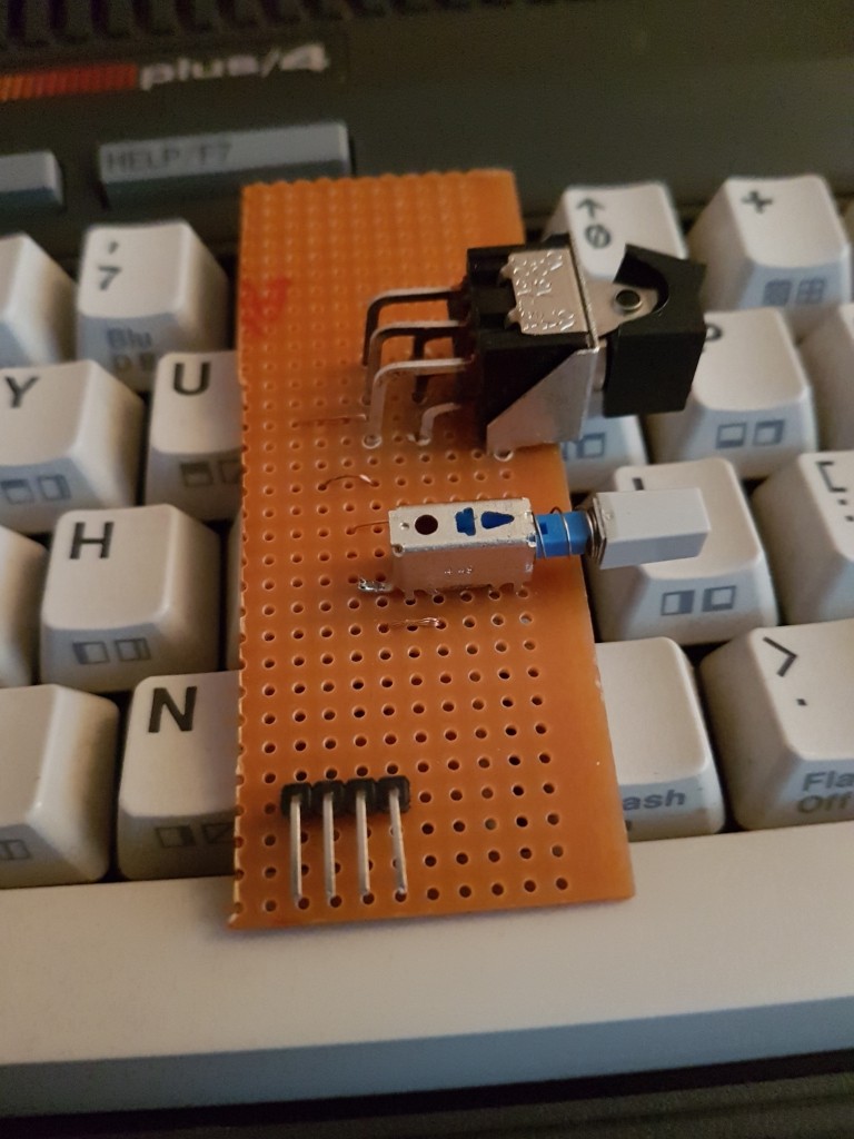 Keyboard modificationWhile it is possible to use the original ribbon cable, it is very fragile and gives many problems, so it's best to remove it and replace it with a right angled pin header, doing this will save you the headache of working out how the ribbon cable actually connects to the KeyrahV2. If you're completely insane and want to do it that way then look at this picture for a clue on what to do, although please be aware in this picture the black ribbon connector was mistakenly mounted upside down. Please see the section at the bottom for more info on this.So the correct way to connect the keyboard to the KeyrahV2 is to remove all eighteen of the tiny screws from the back of the keyboard, including the screw under the foam protection. then desolder the leads connecting to the Shift Lock toggle switch. Be careful as some of the keys will fall out if you turn the case the right way up. This will expose the underside of the keyboard's circuit board. Desolder the ribbon cable from the board, and cut the pin header to size then solder it in to place (it fits in exactly). While you're here you can unsolder the LED from the board so you can connect it direct to the power board.
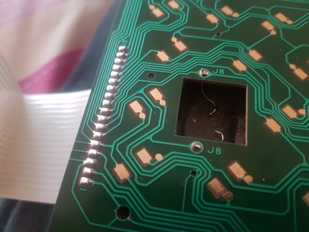


 Now you can use standard jumper cables to connect the two parts together.
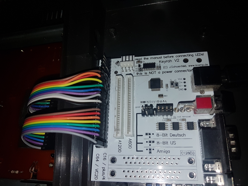
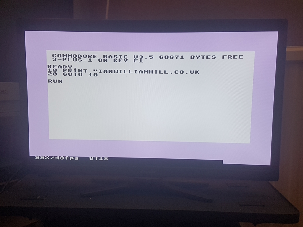
 KeyrahV2 connectionNow you can connect it all back up and this time connect the KeyrahV2 to the Pi.The KeyrahV2 emulates a standard USB keyboard, there is a three position switch which changes the keymapping from positional to symbolic, I leave my switch in the down position. Note the up momentary position is supposed to send a ACPI signal to the host to shutdown, but it does not work in Linux.The joystick sockets are interpreted as keypresses, so you will need to set them up in Vice later.If the letter keys on the Plus 4 keyboard do not match what letters appear on the screen, then you may have the cable connected incorrectly, or even the wrong way round. But you will find the Plus 4 keymap within Vice isn't exactly right either, but the letters and numbers should be right at least. If the F1 key doesn't print SYS1525 : 3-PLUS-1 on the screen then it's connected the wrong way round.
KeyrahV2 modificationYou can cut the little strip off to make it easier to fit inside the Plus 4 case. Note I had already soldered the Plus 4's keyboard connector onto it.
KeyrahV2 connectionNow you can connect it all back up and this time connect the KeyrahV2 to the Pi.The KeyrahV2 emulates a standard USB keyboard, there is a three position switch which changes the keymapping from positional to symbolic, I leave my switch in the down position. Note the up momentary position is supposed to send a ACPI signal to the host to shutdown, but it does not work in Linux.The joystick sockets are interpreted as keypresses, so you will need to set them up in Vice later.If the letter keys on the Plus 4 keyboard do not match what letters appear on the screen, then you may have the cable connected incorrectly, or even the wrong way round. But you will find the Plus 4 keymap within Vice isn't exactly right either, but the letters and numbers should be right at least. If the F1 key doesn't print SYS1525 : 3-PLUS-1 on the screen then it's connected the wrong way round.
KeyrahV2 modificationYou can cut the little strip off to make it easier to fit inside the Plus 4 case. Note I had already soldered the Plus 4's keyboard connector onto it.
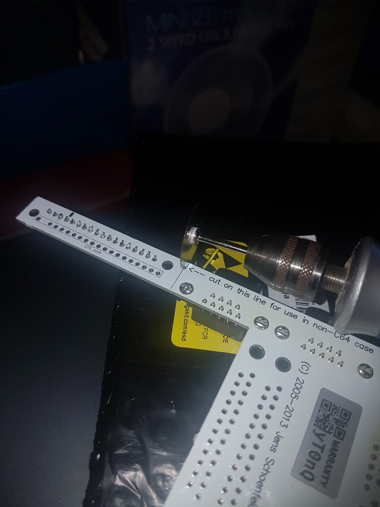
 If you've swapped the ribbon cable for a pin header this piece can be discarded.
Power switch and reset button boardThe power switch is easy, it just goes inline with the power lead to the Pi, so cut that USB cable and solder it. Here's an image I crudely made that shows how to wire up the switch and button, you can see I connect the LED to the switched side of the switch so it's showing power is being supplied to the Pi, you could connect it to a GPIO pin on the Pi to have some control of it, although be aware that the Combian64 image has removed the RPI.GPIO libraries for speed reasons. However, you will need to reinstall them for the reset button anyway.
If you've swapped the ribbon cable for a pin header this piece can be discarded.
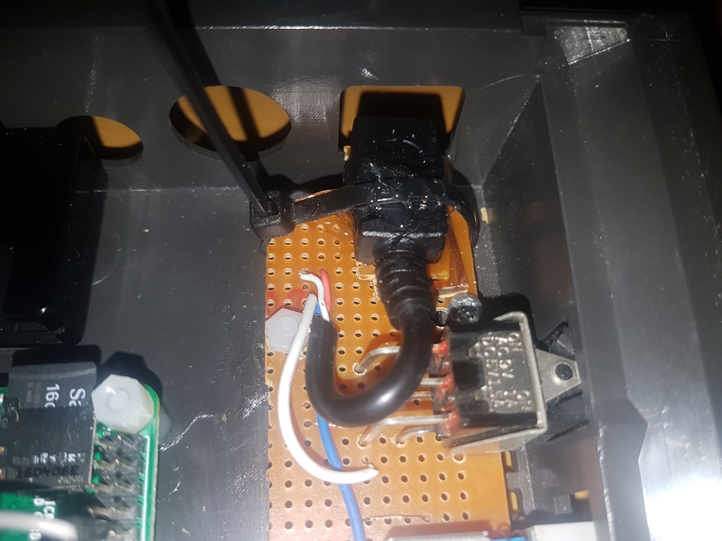
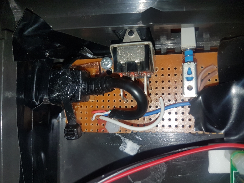
Power switch and reset button boardThe power switch is easy, it just goes inline with the power lead to the Pi, so cut that USB cable and solder it. Here's an image I crudely made that shows how to wire up the switch and button, you can see I connect the LED to the switched side of the switch so it's showing power is being supplied to the Pi, you could connect it to a GPIO pin on the Pi to have some control of it, although be aware that the Combian64 image has removed the RPI.GPIO libraries for speed reasons. However, you will need to reinstall them for the reset button anyway. The switch from the Plus 4 has six pins coming out of it, the reset button has three, they are just toggle switches, you only need to use two pins on each component for them to work. You can use a mulitmeter on continuity mode to check which pins to use.One point to be aware of is some of the cheap micro USB sockets I used for the power connector on this, and various other projects, didn't use the red and black wires for power as you would expect, but rather blue, white, green or others. Here it was red and white, but white was positive and red was negative. It just seems to be random, so check with a multimeter to be sure.The wires from the reset button will go to the fifth and sixth pins down on the left hand row of header pins of the Pi when the Micro SD card is at the top. (GPIO17 and ground) It won't work yet, you have to install the GPIO libraries, a script to monitor the GPIO pins, and modify the startup sequence of Combian64, more on this later.
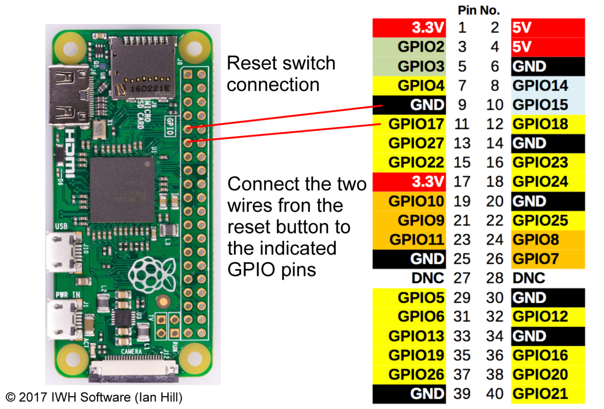 Here are some images to give you an idea of how it looks. I mounted it with holes drilled in the board to line up with one of the original PCB mounting screws, and then plastic standoffs glued to the case, I had to file them down slightly to match the height of the original mounting post.

 You can see in the third picture I removed the pin headers and soldered the wires direct, as it caused too much of a voltage drop at the Pi and I was getting the lightning bolt on the screen, the pins remaining are for the reset button and the LED.
LED connectionThe LED does not work when the keyboard is connected to the KeyrahV2, so I desoldered the wires for the LED so they could go direct to the power board, if you want to reuse the original LED, you will need a 150 Ohm resistor installed in series with it, (if you put 5V on the original LED, it'll just burn out) but I replaced mine with a 5V green LED. If you want to replace the LED you will need to file down a standard round LED to fit, almost to the metal inside. Just keep filing at it until it fits. Remember that the flattened side is the negative pin, The original LED is a weird size and is not available, or i couldn't find it.
You can see in the third picture I removed the pin headers and soldered the wires direct, as it caused too much of a voltage drop at the Pi and I was getting the lightning bolt on the screen, the pins remaining are for the reset button and the LED.
LED connectionThe LED does not work when the keyboard is connected to the KeyrahV2, so I desoldered the wires for the LED so they could go direct to the power board, if you want to reuse the original LED, you will need a 150 Ohm resistor installed in series with it, (if you put 5V on the original LED, it'll just burn out) but I replaced mine with a 5V green LED. If you want to replace the LED you will need to file down a standard round LED to fit, almost to the metal inside. Just keep filing at it until it fits. Remember that the flattened side is the negative pin, The original LED is a weird size and is not available, or i couldn't find it.
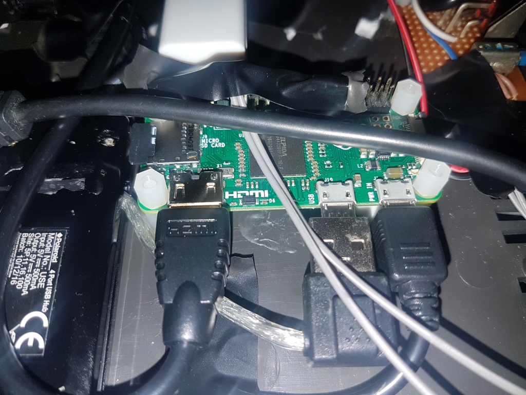
 First assembly attemptNow it's just a case of putting the whole lot into the case and working out where to put it all, there isn't a lot of room in the Plus 4's case, so the bulky parts will have to go at the back, which means some of the port holes will be blocked. You may find it worthwhile to shorten some of the cables as long cables take up a surprising amount of room.Just be careful when pushing the Pi into place or you may end up with this...
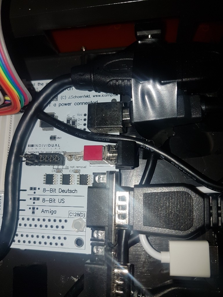
 Yes, I did swear, a lot, much more than normal!!!All the components are mounted with no holes being drilled into the case. I used the original port holes for the sockets as best as I could, the HDMI video socket fits into the original hole for the video monitor socket, and the micro USB socket fits in the hole for the original Power socket, but due to the KeyrahV2 and Pi having to be at the back of the case blocking access to some of the ports, I had to use the large User Port hole for the USB ethernet adaptor and joystick extension, and finally I squeezed a USB socket in the Memory Expansion port by the KeyrahV2.


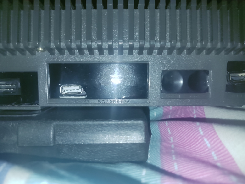 You can see I temporaraly blanked the remaining smaller holes with black tape and the larger holes with black plastic
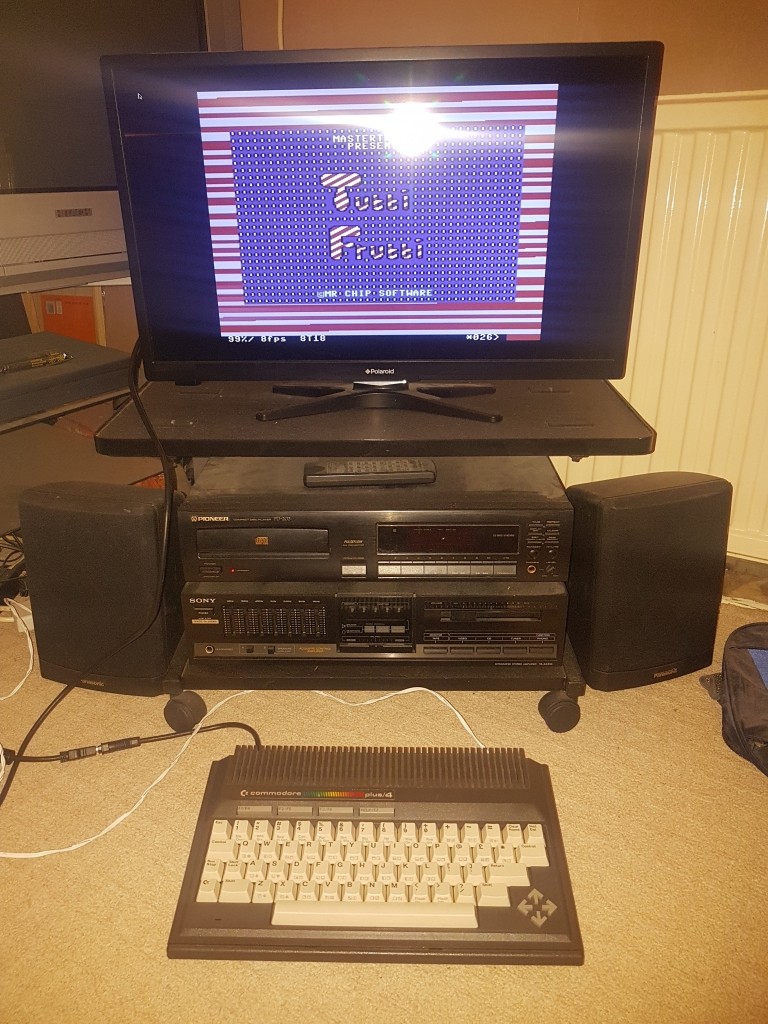
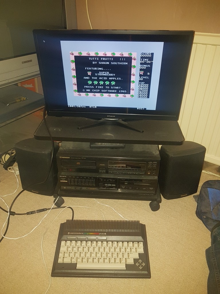
Final assemblyHere are some picures of my final assembly as a guide, yes it is cramped in there.
You can see I temporaraly blanked the remaining smaller holes with black tape and the larger holes with black plastic
Final assemblyHere are some picures of my final assembly as a guide, yes it is cramped in there.
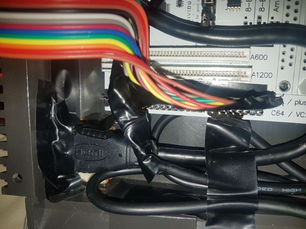

 The boards are held in place with the original PCB mounting posts where possible, and short plastic standoffs where not. The USB hub, USB Ethernet adaptor etc are held down with double sided tape, the HDMI and Micro USB sockets are propped up with thin strips of wood covered in epoxy glue. And finally the cables and the pin header jumper wires are kept in place with normal insulation tape. All of this can be removed at a later date, if I decide to put it back to it's original condition.
Combian64 software setup and issuesThe Combian64 software is mostly set up to work out of the box, however there are some issues that need addressing before we can start playing games on the Plus 4.1. I can NOT get WIFI to work, I tried everything I can think of, but something has been removed and it just won't work. That's why I have a USB to Ethernet adaptor, it connects fine via Ethernet, even when using my laptop as a bridge.2. The boot partition is NOT in a format Windows can access, so you have to edit it within Combian643. The RPI.GPIO libraries have been removed. You can install them from the repositories.4. The nano text editor is not installed. You have to use the editor within Midnight Commander (mc) to edit anything. You can install nano from the repositories.5. The default screen resolution is 640x480@60Hz, there is a mistake in the config.txt, you can change it by typing mc, then navigating to the file with the cursor keys and pressing the edit function key (F4). Change the incorrect Hdmi entry to hdmi, for best results within the emulation, change the values to hdmi_group=1 and hdmi_mode=18, this will correctly match the original PAL hardware's resolution (albeit progressive and not interlaced) and fill the screen.6. Vice starts way before rc.local does, so when you add the script to monitor the reset button to rc.local, it won't start until you exit Vice. So you have to add it to init.d.7. If you decide to update with apt-get, auto login will be disabled, you can re-enable it, but it's a pain, and it makes the system slightly slower due to reinstalling some removed packages. So don't update! BTW I did this and eventually found out by pure luck the username and password are root and 1234, they are not documented anywhere, but Combian is based on Amibian, so I tried the documented Amibian username and password.8. Vice clears it's config file while it's running and writes it out on exit, so if you use the reset button while Vice is running, or turn it off, you can wipe the settings back to default, which are not optimised for the Pi. So until I can find some overly complicated way of fixing this, exit Vice before reset or shutdown.9. All the different machines Vice can emulate have separate config files, so if you want to run the Plus 4, C64, and Vic 20, you will have to set up each machine separately. Don't forget to save the changes (or turn on Save on exit.)
Joystick setupTo set up the joysticks you need to go into the settings and allow the use of the keyset joystick, (joystick settings are in machine settings). You need to define the keyset for each joystick. For single joystick setups, setup keyset 1, and then just swap joysticks in the Vice menu when necessary. For two joystick setups, set up both keyset 1 and 2 via the relevant port, you'll find port one will always be port one and vise-versa, even if you swap joysticks around. Finally set the Joystick device 1 (or 2) to Keyset 1 (or 2). Games seem to use both ports, so either select Swap joystick ports in the menu, or swap the actual ports when necessary.You will need to do this for every instance of Vice you intend to run (C64, Vic20 etc)Don't forget to save it when done.
Installing gamesTo get "games" installed on the Plus 4, it's best to use a USB memory stick, so find one and create folders on it for the Plus 4, C64, and Vic 20, then copy the game images into them. I find using .d64 .tap .crt and .prg images works best, (.d64 and .tap can be zipped to save a few KB's) then copy them over manually in Midnight Commander (mc).Navigate to /media/usb to find the USB stick, press tab to swap to the second window, then navigate to /root/combian64/games, press tab to swap back, then highlight the folder you want to copy and press copy (F5) then enter, repeat for any other folders you may want to copy. Once complete press quit (F10) to exitTo load games press F8 and select Autostart image and navigate to the game file.Keyboard setupYou may find it easier to go into the Vice menu (F8) and go into Settings managment and scroll down to the bottom to Define UI keys and change the default keys to keys that are available on the Plus 4 keyboard. Activate menu works nicely on HELP/F7. Menu up, down, left, right can be the cursor keys, Menu select can be Return, and Menu exit can be Escape. Don't forget you will need to do this for the C64 and Vic 20 machines as well.Once these are set you will only really need a USB keyboard if you exit Vice to the command line.
Reset button configurationConnect the Pi to the network, unfortunately you will have to do this with an Ethernet cable as WIFI just does not work, if you're using a Pi Zero you can use a USB to Ethernet adaptor.Run this command and wait for it to finish...
The boards are held in place with the original PCB mounting posts where possible, and short plastic standoffs where not. The USB hub, USB Ethernet adaptor etc are held down with double sided tape, the HDMI and Micro USB sockets are propped up with thin strips of wood covered in epoxy glue. And finally the cables and the pin header jumper wires are kept in place with normal insulation tape. All of this can be removed at a later date, if I decide to put it back to it's original condition.
Combian64 software setup and issuesThe Combian64 software is mostly set up to work out of the box, however there are some issues that need addressing before we can start playing games on the Plus 4.1. I can NOT get WIFI to work, I tried everything I can think of, but something has been removed and it just won't work. That's why I have a USB to Ethernet adaptor, it connects fine via Ethernet, even when using my laptop as a bridge.2. The boot partition is NOT in a format Windows can access, so you have to edit it within Combian643. The RPI.GPIO libraries have been removed. You can install them from the repositories.4. The nano text editor is not installed. You have to use the editor within Midnight Commander (mc) to edit anything. You can install nano from the repositories.5. The default screen resolution is 640x480@60Hz, there is a mistake in the config.txt, you can change it by typing mc, then navigating to the file with the cursor keys and pressing the edit function key (F4). Change the incorrect Hdmi entry to hdmi, for best results within the emulation, change the values to hdmi_group=1 and hdmi_mode=18, this will correctly match the original PAL hardware's resolution (albeit progressive and not interlaced) and fill the screen.6. Vice starts way before rc.local does, so when you add the script to monitor the reset button to rc.local, it won't start until you exit Vice. So you have to add it to init.d.7. If you decide to update with apt-get, auto login will be disabled, you can re-enable it, but it's a pain, and it makes the system slightly slower due to reinstalling some removed packages. So don't update! BTW I did this and eventually found out by pure luck the username and password are root and 1234, they are not documented anywhere, but Combian is based on Amibian, so I tried the documented Amibian username and password.8. Vice clears it's config file while it's running and writes it out on exit, so if you use the reset button while Vice is running, or turn it off, you can wipe the settings back to default, which are not optimised for the Pi. So until I can find some overly complicated way of fixing this, exit Vice before reset or shutdown.9. All the different machines Vice can emulate have separate config files, so if you want to run the Plus 4, C64, and Vic 20, you will have to set up each machine separately. Don't forget to save the changes (or turn on Save on exit.)
Joystick setupTo set up the joysticks you need to go into the settings and allow the use of the keyset joystick, (joystick settings are in machine settings). You need to define the keyset for each joystick. For single joystick setups, setup keyset 1, and then just swap joysticks in the Vice menu when necessary. For two joystick setups, set up both keyset 1 and 2 via the relevant port, you'll find port one will always be port one and vise-versa, even if you swap joysticks around. Finally set the Joystick device 1 (or 2) to Keyset 1 (or 2). Games seem to use both ports, so either select Swap joystick ports in the menu, or swap the actual ports when necessary.You will need to do this for every instance of Vice you intend to run (C64, Vic20 etc)Don't forget to save it when done.
Installing gamesTo get "games" installed on the Plus 4, it's best to use a USB memory stick, so find one and create folders on it for the Plus 4, C64, and Vic 20, then copy the game images into them. I find using .d64 .tap .crt and .prg images works best, (.d64 and .tap can be zipped to save a few KB's) then copy them over manually in Midnight Commander (mc).Navigate to /media/usb to find the USB stick, press tab to swap to the second window, then navigate to /root/combian64/games, press tab to swap back, then highlight the folder you want to copy and press copy (F5) then enter, repeat for any other folders you may want to copy. Once complete press quit (F10) to exitTo load games press F8 and select Autostart image and navigate to the game file.Keyboard setupYou may find it easier to go into the Vice menu (F8) and go into Settings managment and scroll down to the bottom to Define UI keys and change the default keys to keys that are available on the Plus 4 keyboard. Activate menu works nicely on HELP/F7. Menu up, down, left, right can be the cursor keys, Menu select can be Return, and Menu exit can be Escape. Don't forget you will need to do this for the C64 and Vic 20 machines as well.Once these are set you will only really need a USB keyboard if you exit Vice to the command line.
Reset button configurationConnect the Pi to the network, unfortunately you will have to do this with an Ethernet cable as WIFI just does not work, if you're using a Pi Zero you can use a USB to Ethernet adaptor.Run this command and wait for it to finish...
apt-get install nano python-dev python-rpi.gpio
nano /root/button.sh
#!/usr/bin/python

import RPi.GPIO as GPIO
import os
import time

GPIO.setmode(GPIO.BCM)
GPIO.setup(17, GPIO.IN, pull_up_down = GPIO.PUD_UP)

print "Starting button.sh..."

pressed_time = 0
button = 0
while button == 0:
  time.sleep(0.50)
  while GPIO.input(17) == False:
     time.sleep(1)
     pressed_time=pressed_time + 1
     button = 1
     if pressed_time == 3:
        break

if pressed_time<2:
  os.system("sudo reboot")
elif pressed_time>=2:
os.system("sudo shutdown now")chmod 777 /root/button.sh
python /root/button.sh
cd /etc/init.d
cp aaabatterysupportedremote aaaabutton.sh
nano aaaabutton.sh
cd /root/combian64
./xplus4
cd /root
python ./button.sh &
chmod 777 aaaabutton.sh
cp aaaabutton.sh /etc/rcS.d/S01aaaabutton.sh
nano /lib/systemd/system/getty@.service
ExecStart=-/sbin/agetty --noclear %I $TERM
ExecStart=-/sbin/getty/ --noclear -a root %I $TERM


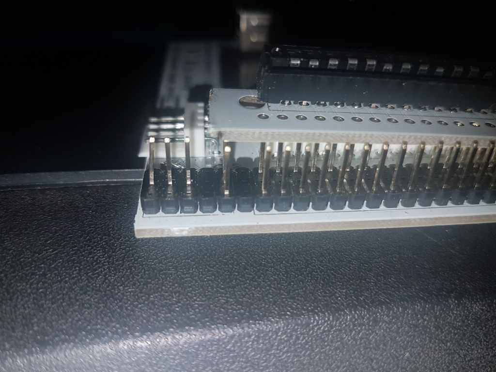
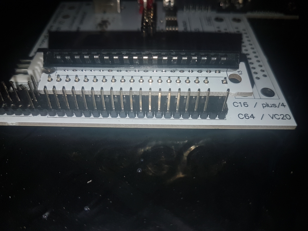
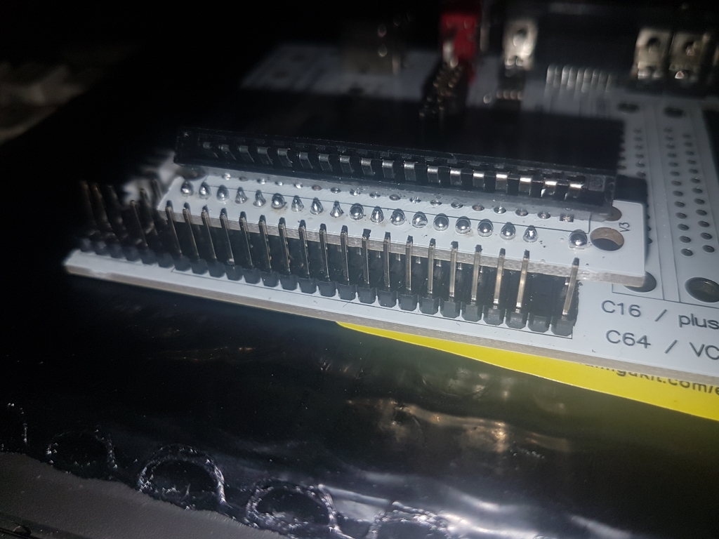
 Using the KeyrahV2 with the ribbon cableThis is the definition of insanity!It is not documented anywhere how to do this, it only says "Part of the base PCB must be used", it took me a while to figure it out, I even twitter messaged other KeyrahV2 users for help, and I still got it wrong. AND to make it worse, it's too high to sit where it naturally wants to in the case, so you have to bend the ribbon cable at a 90 degree angle to mount it so it fits with the case fitted together, which will probably break it.But if you still want to try it, follow this picture guide...Note: The black ribbon cable connector from the Plus 4 PCB is upside down in these pictures, so turn it round 180 degrees before soldering it to the board.


 BTW if you try and decide to change your mind, removing it is a right pain in the proverbial body part. You will NOT just be able to desolder it, I had to cut it in to sections and remove it piece by piece.

 Just replace it with a pin header, it's much less hassle.Enjoy your "new" Commodore Plus/4!


